

Arduino Due - PIO
Introduction
This is the first in a series of articles that will cover the inner workings of the Arduino Due 32bit board based on the Atmel SAM3X8E ARM Cortex-M3 processor.[1] Each article in this series will cover a discrete sub-system within the micro controller and in this first article we will begin with a discussion of the Parallel I/O controller.
The Arduibo Due is powered by 3.3V and it's I/O lines ARE NOT 5V tolerant. Each pin can source a current of 3 mA or 15 mA, depending on the pin, or sink a current of 6 mA or 9 mA, depending on the pin with a total of 130mA DC Output Current on all I/O lines.
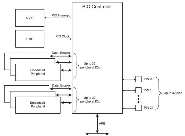
The Peripheral Input Ouput (PIO) controller is tightly integrated with other sub-systems such as the Nested Vector Interrupt Controller (NVIC) and the Power Management Controller (PMC). The NVIC Controller uses a relocatable vector table that offers very fast, prioritized interrupt capabilties. The Power Management Controller is designed to save power by enabling and disabling the system and peripheral clocks.
Pin Multiplexing
Pin multiplexing is nothing new and the Due is no different. As well as being a digital I/O pin each pin can have up to 2 peripheral lines, lines that affect only the output, the input is always connected to the pins input. Optional input Glitch and Debounce filters may be independently programmed for each I/O line but for the simpe examples in this article we will not make use of or explain there usage. We will cover this topic in a future article!
To use the pin in the digital I/O mode all that's needed is to enable the pin in the controller. To use the peripheral functionality of the pin disable the pin and set the AB Select Register to the approperiate setting, an example follows.
- PIOport->PIO_PER = (1 << pin) - Enables the digital I/O on the port and pin specified.
- PIOport->PIO_PDR = (1 << pin) - Disables digital I/o on the port and pin specified.
-
- PIOport->PIO_ABSR = ~(1 << pin) - AB Select Register, select A peripheral.
- PIOport->PIO_ABSR = (1 << pin) - selectes the B peripheral.
I use the Atmel-ICE to program the board from Atmel Studio 6.2 using the C++ language. As I get more proficient with this board I will be creating some C++ libraries to control some of the more popular peripherals.
Power Management
The Power Management Controller controls the clock used but the PIO Controller and in order to save power the clock is by default PIO clock is disabled. The PIO clock needs to be enabled if the I/O line is configured as Input and in some cases when configured as peripheral. In our example application, since we are using an input to check switch status the clock is enabled for the PIO Control on PORTC. (Refer to data sheet Section 11.1 Peripheral Identifiers for a full list of IDs)
Interrupt Generation
The Nested Vectored Interrupt Controller (NVIC)[5] is an embedded interrupt controller that supports low latency interrupt processing and provides up to 16 interrupt priority levels. It is closely integrated with the PIO Controller and requires the NVIC to be programmed first, additionally PIO Controller interrupts can be generated only if the PIO Controller clock is enabled. To configure interrupts for a line we must not only configure the PIO Controller using the PIO_IER to enable interrupts but we must also configure the NVIC Controller to be able to handle the interrupt. To enable the NVIC Controller for PORTC we use the NVIC_EnableIRQ method with the appropriate peripheral type specified, in our case PIOC_IRQn. Section 12.20 in the data sheet provides information about the NVIC and the methods used to configure it.
Hardware
We're going to start out with a basic circuit to showcase a portion of the PIO controllers features. The Atmel Studio solution provided in the download is divided into 2 projects; Due-PIO-Basic that uses polling to check status of a tactile switch on PORTC.PIN12 and set the state of an onboard LED, normally high and low when the switch is pressed, and the Due-PIO-Interrupt project that uses an interrupt service routine to toggle the state of the onboard LED.
PIO with polling input
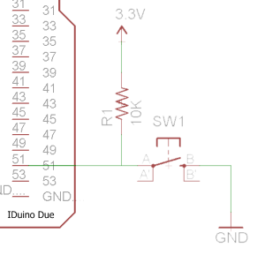
Example solution Due-PIO-Basic uses a tactile switch that when pressed dims a normally lit onboard LED. The switch is configured as an input on PORTC.PIN12 and the onboard LED is located on PORTB.PIN27.
void InitPIO()
{
	//We need to associate clock with Port C so we can read input
    //A list of Peripheral ID's can be found on Page 47 in the datasheet.
	PMC->PMC_PCER0 = _BV(ID_PIOC);
	//Enable PB27 and PC12 (Peripheral Enable Register)
	PIOB->PIO_PER = PIO_PB27;
	PIOC->PIO_PER = PIO_PC12;

	//Set B27 as output (Output Enable Register)
	PIOB->PIO_OER = PIO_PB27;

	//Set C12 as input (Ouput Disable Register)
	PIOC->PIO_ODR = PIO_PC12;

	//Disable pull-up on both pins (Pull Up Disable Register)
	PIOB->PIO_PUDR = PIO_PB27;
	PIOC->PIO_PUDR = PIO_PC12;
}
Very simple polling routine that checks the Pin Data Status Register's status every delay period and sets the state of the LED accordingly.
while (1)
{
	//Read the PORTC Pin Data Status Register checking Pin 12 for a change of state
	//  and set on board LED appropriately.
	if ((PIOC->PIO_PDSR & PIO_PC12) == PIO_PC12)
		PIOB->PIO_SODR = PIO_PB27;  //Set Ouput Data Register
	else
		PIOB->PIO_CODR = PIO_PB27;  //Clear Output Data Register

	delay();
}
PIO using Interrupt
Example solution Due-PIO-Interrupt uses an interrupt service routine to handle an interrupt when the falling edge, switch closure occurs and an toggle the state of the onboard LED.
void InitPIO()
{
	//Enable PB27 and PC12
	PIOB->PIO_PER = PIO_PB27;
	PIOC->PIO_PER = PIO_PC12;

	//Set B27 as output
	PIOB->PIO_OER = PIO_PB27;

	//Set C12 as input
	PIOC->PIO_ODR = PIO_PC12;

	//Disable pull-up on both pins
	PIOB->PIO_PUDR = PIO_PB27;
	PIOC->PIO_PUDR = PIO_PC12;

	//We need to associate clock with Port C so we can read input
	PMC->PMC_PCER0 = _BV(ID_PIOC);
	//The interrupt signals of the thirty-two channels are ORed-wired together to generate
	//	a single interrupt signal to the Nested Vector Interrupt Controller (NVIC).
	NVIC_EnableIRQ(PIOC_IRQn);

	//In the next few statements we are setting up the pin to trigger on the falling edge.
	//	We do this because we have an external pull-up resistor and when the button is
	//	pressed the line is driven low.

	//Additional Interrupt Modes Enable Register
	PIOC->PIO_AIMER = PIO_PC12;
	//Edge Select Register
	PIOC->PIO_ESR = PIO_PC12;
	//Falling Edge/Low Level Select Register
	PIOC->PIO_FELLSR = PIO_PC12;
	//Finally enable interrupts on PORTC.PIN12
	PIOC->PIO_IER = PIO_PC12;
}
The following code is the Interrupt service routine for the edge triggered interrupt that is run when the switch is closed.
void PIOC_Handler()
{
    //Since the interrupt could be any pin on PORTC we need to
    //  check if PC12 is the one triggering the interrupt.
	if ((PIOC->PIO_ISR & PIO_PC12) == PIO_PC12)
	{
		status = !status;
		if (status)
			PIOB->PIO_SODR = PIO_PB27;
		else
			PIOB->PIO_CODR = PIO_PB27;
	}
}
Summary
While doing research for this article all the code examples I could find were wrote for the Arduino IDE and therefore most of the heavy lifting is done using the set of libraries provided.
References
[2]Arduino Due, schematics, eagle files, and more, https://www.sparkfun.com/products/11589
[3]Paul Rako, The new Atmel-ICE debugger is here. http://atmelcorporation.wordpress.com/2014/03/25/the-new-atmel-ice-debugger-is-here
[4]Keil, Nested Vector Interrupt Controller, http://www.keil.com/support/man/docs/gsac/gsac_nvic.htm
Download Here