

AVR Asm - 101
In order to learn the assembler programming language some knowledge must be known about the hardware we are using. In this tutorial we will start with a brief introduction to the inner workings of the AVR micro controller then move on to pure assembler and finally show how to mix 'C' and assembler languages.
- Introduction
- Memory Configuration
- Accessing Memory
- Input/Output
- The Language
- Mixing languages
- Complete example assembler program
- Conclusion
- References
Introduction
Why on earth would anyone want to program in a low level language like Assembler when there are languages such as C, C++ and others that provide a layer of abstraction that takes all the drudgery out of programming?
- Some people are masochists.
- The code generated by the high level compiler won't fit in MPU's memory space.
- We have a need for speed.
- We are control freaks and need to control every aspect of the applications flow.
There is also another good reason to learn assembler, the more you know about the inner workings of the processor the more capable a programmer you will become. And even if you do decide that you need to write portions of your code in Assembler you are not restricted to just using Assmbler or higher level language we can mix them as long as we observe a few simple rules. For instance we could use 'C' as our main language but write the interrupt routines in assembler.
Memory Configuration
AVR uses a Harvard architecture which is an architecture with separate memories and buses for program and data. Instructions in the program memory are executed with a single level pipelining. This means that while one instruction is being executed, the next instruction is pre-fetched from the program memory. This concept enables instructions to be executed in every clock cycle. The figure below illustrates the memory map for a typical AVR device. The actual memory configuration will depend on the particular MPU being used, check the data sheet.

Accessing Memory
Because of the disjointed nature of AVR's architecture each memory segment needs to be accessed in a different fashion. Instructions are provided for program and data memory access and memory can be retrieved or writen in the same way that it is accessed in most other processors. EEPROM access will be covered in it's own section because it is a different beast in Atmel and most other micro controllers.
Program Memory
Program Memory should be thought of as read only memory hence there are only two instructions for working with it Load Program Memory (LPM) and Store Program Memory (SPM) and unless you are writing self-modifying code there is really no need to write to Program Memory.
Data Memory
In this section we will cover the many instructions dedicated to working with Data Memory. The information was taken from the ATMega1280 Datasheet since not all processors use these instructions in the same fashion you will need to refer to the Datasheet for the particular processor you are using.
The instructions listed in this section are limited to a 64K data segment and some less but processors that have a larger data space there is a special register, RAMPD that can be used in conjunction with some of the indirect instructiions to access memory beyond the 64K limit. For accessing Program memory above 64K there is also a special register, RAMPZ available.
The LDS instruction loads a single byte of data from the data space to a register and depending on whether it uses an 8 or 16 bit address the Opcode size is either 16-bit or 32-bit respectively. Similar instructions are available to transfer a single byte of data from a register to data space using the STS instruction.
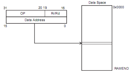
Instructions that use this format are;
LDS - Load Direct from Data Space
Syntax:     LDS Rd,k        0«d«31, 0«k«65535
Example:    LDS R0,0x0100
LDS (16 bit) - Load Direct from Data Space
Syntax:     LDS Rd,k        16«d«31, 0«k«127
Example:    LDS R16,0x00
STS - Store Direct to Data Space
Syntax:     STS k,Rr        0«r«31, 0«k«65535
Example:    STS 0x0100,R2
STS (16 bit) - Store Direct to Data Space
Syntax:     STS k,Rr        16«r«31, 0«k«127
Example:    STS 0x00,R2
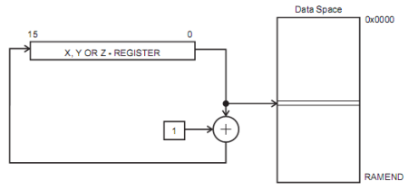
Loads or stores a single byte of data to or from data memory and a register. As can be seen in the image below an immediate value is added to the value in the Y or Z register to derive at the final address of the desired data byte. On devices that have more than 64K data memory area the RAMPY and RAMPZ registers allow for 24-bit addressing.
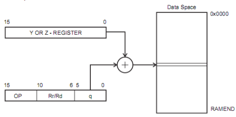
	    LDD - Load Indirect using Y or Z
	    Syntax:     LDD Rd,Y+q    0«d«31, 0«q«63
				    LDD Rd,Z+q
	    Example:    LDD R4,Y+2    ;Load R4 with loc. 0x60
				    LDD R3,Z+4    ;Load R3 with loc. 0x30
This instruction is similar to the Data Indirect with Displacement except it doesn't use a displacement but instead loads indirectly using the X, Y or Z registers.
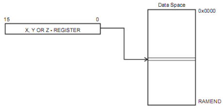
	LD - Load Indirect using X, Y or Z
	Syntax:     LD Rd,X     0«d«31
				LD Rd,Y
				LD Rd,Z
	Example:    LDI R26,0x20
				LD R2,X         ;Load R2 with loc. 0x20
				LDI R28,0x40
				LD R3,Y         ;Load R3 with loc. 0x40
				LDI R30,0x60
				LD R4,Z         ;Load R4 with loc. 0x60
Similar to the Data Indirect instruction this instruction decrements the X, Y or Z register before the data is accessed and like the Data Indirect instruction it allows the registers to be used.
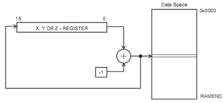
LD - Load Indirect using X, Y or Z
Syntax:     LD Rd,X     0«d«31
			LD Rd,Y
			LD Rd,Z
Example:    LDI R26,0x20
			LD R2,-X         ;Load R2 with loc. 0x1F
			LDI R28,0x40
			LD R3,-Y         ;Load R3 with loc. 0x3F
			LDI R30,0x60
			LD R4,-Z         ;Load R4 with loc. 0x5F
Similar to the Data Indirect instruction this instruction increments the X, Y or Z register after the data is accessed and like the Data Indirect instruction it allows the registers to be used.
	LD - Load Indirect using X, Y or Z
Syntax:     LD Rd,X     0«d«31
			LD Rd,Y
			LD Rd,Z
Example:    LDI R26,0x20
			LD R2,X+         ;Load R2 with loc. 0x20
			LD R2,X          ;Load R2 with loc. 0x21
			LDI R28,0x40
			LD R3,Y+         ;Load R3 with loc. 0x40
			LD R3,Y          ;Load R3 with loc. 0x41
			LDI R30,0x60
			LD R4,Z+         ;Load R4 with loc. 0x60
			LD R4,Z          ;Load R4 with loc. 0x61
EEPROM Memory
Although the program and data memories are fairly straight forward easy to understand and program, the EEPROM is quite another story. In assembly this is not a trivial pursuit and is better done in 'C' where code is provided that handles the reading and writing of EEPROM.
But for those brave soles that are intent on using assembler to read/write to/from EEPROM I have provided (lifted straight from data sheet) code to perform minimal functionality. Refer to the data sheet for your particular device for further information.
Avoid using the lowest EEPROM address, in some instances this lowest address can be trashed and you will lose your data. Since data is writen in the order you declare your variables just declare a bogus variable before any other.
;
;  The EEPROM_Write routine
;
EEPROM_write:
    ;Wait for completion of previous write
    sbic    eecr,eepe
    rjmp    EEPROM_write
    ;Set up the address (r18:r17) to address register
    out     eearh,r18
    out     eearl,r17
    ;Write data (r16) to Data register
    out     eedr,r16
    ;Write logical one to eempe
    sbi     eecr,eempe
    ;Start eeprom write by setting eepe
    sbi     eecr,eepe
    ret
;
;   The EEPROM_Read routine
;
EEPROM_Read:
    ;Wait for the completion of the previous write
    sbic    eecr,eepe
    rjmp    EEPROM_Read
    ;Set up address (r18:r17) in address register
    out     eearh,r18
    out     eearl,r17
    ;Start eeprom read by writing eere
    sbi     eecr,eere
    ;Read data from Data register
    in      r16,eedr
    ret
Input/Output
IO register space is mapped into regular data memory with an offset of 0x20 for most devices meaning that it can be accessed just like any other data memory, this includes the registers for all peripherals such as Timers, USART, Watch Dog Timer, etc..
When used as general I/O ports all ports have read-modify-write functionality and each pin has symmetric capability to drive or sink source. In addition individual pins may be configured as either input or output, have selectable pull-up resistors and have protection diodes to both VCC and GND.
Two special instructions (IN and OUT) are provided for working with I/O registers. An example of how these instructions are used can be viewed in the EEPROM example code.
Register Usage
As a general rule registers used in conjuction with 'C' code follow the general guidelines as listed in the following table. We will be taking a look at these registers when we start mixing languages, they play a very important part in the integration.
| Register(s) | Description |
|---|---|
| r0 | Temporary register - use in interrupts not recommended. |
| r1 | Zero register - can be used for temporary data but must be zero'd after use. |
| r18-r27, r30-r31 | These are general purpose registers and don't need to be saved when using in conjuction with 'C' code. |
| r2-r17, r28-r29 | These are general purpose registers but do need to be saved when using in conjuction with 'C' code. |
Macros
By definition a macro is a group of instructions that you code once and are able to use as many times as necessary. The main difference between a macro and a subroutine is that the macro is expanded at the place where it is used. A macro can take up to 10 parameters referred to as @0-@9 and given as a coma delimited list.
;PUSH_REGS macro
;Example macro that accepts 2 parameters that define the
;registers that are to be pushed onto the stack.
.macro PUSH_REGS
    push    @0
    push    @1
.endmacro
;
;Then to use the PUSH_REGS macro
label:
    ldi         R18,0x00
    ldi         R17,0x02
    PUSH_REGS   R18,R17
    .
    .
;
;And in reality what you end up with is
label:
    ldi         R18,0x00
    ldi         R17,0x02
    push        R18     ;macro code
    push        R17     ;macro code
    .
    .
;
Macros are generally made up of code that gets executed on a routine basis and are kept in libraries so that they may be included where and as needed.
Subroutines
For a problem to be solved it must be broken down into smaller more managable chunks and subroutines allow a programmer to do this. By modularizing our code we are able, as with macros to use subroutines to isolate code that we use often into a reusable libray often reducing the size and conplexity of our applications.
Most programmers are familiar with subroutines whether they call them subroutines, procedures, functions or something else so I don't see the need to explore them in any depth here.
Mixing Languages
The gcc 'C' compiler uses registers in a very consistent manner to pass parameters to and return values from subrountines. If we observe a few simple rules when mixing languages such as 'C' and assembler the integration of the two languages is fairly straight forward. Only 'C' is referenced in this tutorial but I would imagine that many high level languages that use the gcc compiler can be referenced in a similar manner.
When passing parameters to a subroutine Registers r25 through r8, in that order are used. If more parameters then registers need to be passed to the subroutine the stack is used and is not recommended due to a substantial hit to resources. As an additional note register pairs are used regardless of the size of the parameter being passed. This concept and others will be discussed further in the next two sections. Values returned from a subroutine follow the guide lines shown in the following table.
| Register | Description |
|---|---|
| R24 | 8 bit values |
| R24:R25 | 16 bit values |
| R24-R22 | 32 bit values |
| R24-R18 | 64 bit values |
Calling Assembler subroutine from C
By now you should have a pretty good idea of what to expect so I will demonstrate calling an assembly subroutine from 'C' by providing a couple of examples. Each example will have the 'C' code, followed by the resulting disassembled code and finally the assembler subroutine.
In the first example the assembler subroutine adds two 16 bit numbers passed as parameters iParam1 (R25:R24) and iParam2 (R23:R22) and returns the result (R25:R24) to the main 'C' routine.
//Assembly subroutine declaration - keeps the compiler from
//generating a warning concerning implicit declaration.
int AsmSubroutine(int iParam1, int iParam1);
//This is the main 'C' routine
int main()
{
    int iRetVal = 0;

    //Call to our assembler subroutine
    iRetVal = AsmSubroutine(1024, 16);
}
Resulting disassembled code
            iRetVal = AsmSubroutine(1024, 16);
 318:	80 e0       	ldi	r24, 0x00	; 0
 31a:	94 e0       	ldi	r25, 0x04	; 4
 31c:	60 e1       	ldi	r22, 0x10	; 16
 31e:	70 e0       	ldi	r23, 0x00	; 0
 320:	0e 94 ae 01 	call	0x35c	; 0x35c <AsmSubroutine>
 324:	90 93 01 06 	sts	0x0601, r25
 328:	80 93 00 06 	sts	0x0600, r24
Assembler subroutine code
	.section	.text

	;The global directive declares AsmSubroutine as global for linker.
	;The AsmSubroutine label must follow the global directive.
	.global 	AsmSubroutine
AsmSubroutine:
	add		R25,R23
	adc		R24,R22
	ret
	.end
In the second example the assembler subroutine adds two 8 bit numbers passed as parameters iParam1 (R24) and iParam2 (R22) and returns the result (R24) to the main 'C' routine.
//Assembly subroutine declaration - keeps the compiler from
//generating a warning concerning implicit declaration.
unsigned char AsmSubroutine(unsigned char, unsigned char);
//This is the main 'C' routine
int main()
{
    unsigned char ucRetVal = 0;

    //Call to our assembler subroutine
    ucRetVal = AsmSubroutine(32, 16);
}
Resulting disassembled code
    iRetVal = AsmSubroutine(32, 16);
 318:	80 e2       	ldi	r24, 0x20	; 32
 31a:	60 e1       	ldi	r22, 0x10	; 16
 31c:	0e 94 aa 01 	call	0x354	; 0x354 <AsmSubroutine>
 320:	80 93 00 06 	sts	0x0600, r24
Assembler subroutine code
	.section	.text

	;The global directive declares AsmSubroutine as global for linker.
	;The AsmSubroutine label must follow the global directive.
	.global 	AsmSubroutine
AsmSubroutine:
	add		R24,R22
	ret
	.end
As can be seen from the two examples the parameters passed in use a register pair per parameter so in the second example even though we are passing two 8 bit values the compiler puts each 8 bit value in the lower of the register pair.
Calling C subroutine from Assembler
When calling a 'C' subroutine from assembler the same rules and registers apply, load the proper parameters into R25-R18 and expect the results in the corresponding registers. To illustrate this concept we will add two 16 bit numbers as we did in the first example above but after calling the Assembler subroutine from C we will just make a call to a C routine that will add the two numbers and return the result and as you will see the same results will be obtained.
int AsmSubroutine(int, int);
int AddCSubroutine(int, int);
int main()
{
    int iRetVal = 0;

    iRetVal = AsmSubroutine(1024, 16);
}
//Adds to 16 bit numbers.
int AddCSubroutine(int p1, int p2)
{
	return p1 + p2;
}
If you compare this with the first example above you will notice that they are identical.
        iRetVal = AsmSubroutine(1024, 16);
 320:	80 e0       	ldi	r24, 0x00	; 0
 322:	94 e0       	ldi	r25, 0x04	; 4
 324:	60 e1       	ldi	r22, 0x10	; 16
 326:	70 e0       	ldi	r23, 0x00	; 0
 328:	0e 94 b2 01 	call	0x364	; 0x364 <AsmSubroutine>
 32c:	90 93 01 06 	sts	0x0601, r25
 330:	80 93 00 06 	sts	0x0600, r24
The assembler subroutine merely calls the 'C' subroutine demonstrating that the same registers are used throughout the process.
    .section	.text
	.global 	AsmSubroutine
AsmSubroutine:
	call	AddCSubroutine
	ret
	.end
Complete example assembler program
This simple but complete assembler program demonstrates the basic components needed for an assmbler application. The application reads data from program memory and writes it in reverse order into data memory demonstrating how the program and data memories are accessed. The example is well commented so no further explanation is provided.
/*
	AVR Assembler Tutorial Example
	Author: Mike Hankey
	Date:	7/17/2010
	Hardware: 	none
	Assembler: 	AVR Assembler 2.0
	Purpose: Read msg data from program memory and write
	it to Data segment in reverse order.
	Although this is a very simple example of an assmbler
	program it contains many of the elements that are
	needed in most real assembler applications.

	You will need to set "Additional include path" in
	Project->Assembler Options to the m1280def.inc or
	the appropriate inc file for your processor to the
	path where you installed AVRStudio.  An example path
	might be;

	C:\Program Files\AVRStudio\AvrAssembler2\Appnotes\m1280def.inc
*/
.NOLIST
.include "m1280def.inc"
.LIST
/*
	Macro to set the Stack Pointer to end of ram
	Input Parameters: none
*/
.macro SET_STACK
	ldi	r16, LOW(RAMEND)
	out	spl, r16
	ldi	r16, HIGH(RAMEND)
	out	sph, r16
.endmacro
/*
	Data segment
	All we can do here is reserve a	portion of the data
	segment for our target string.  We cannot initialize
	data in this segment. We are setting aside 32 bytes
	(0x20) for our target string.
*/
.dseg
msgd:
	.byte	0x20
/*
	Code Segment
	Use .org to set the base address in code segment where
	we want the code to begin, in this case 0 or beginning
	of the segment.  The first part of the code segment is
	reserved for the interrupt/jump table and the first
	item in the table is the reset vector which we put a
	jump instruction to the first line of our code..  Since
	we are not declaring any other interrupts we can ignore
	the	rest of the table and just add a 2nd .org setting
	the start label or beginning of the	code at location
	0x20.
*/
.cseg
.org 0
	rjmp	start
/*
	End of Jump table and start of our code.
*/
.org 0x20
start:
	SET_STACK			;Invoke our macro to set stack ptr
	/*
		The Z-resister is used to access Program memory.
		This 16 bit	register pair is used as a 16 bit ptr
		to the Program Memory where the most significant 15
		bits select the word address and the LSB is the
		Low/High bit select therefore we must multiply the
		address by 2 by shifting left one place.  We could
		have also have just multiplied by 2;
			ldi	ZH,high(msg*2)
			ldi	ZL,low(msg*2)
		either way is acceptible!
	*/
    ldi		ZH,high(msg<<1) ;set z pointer to message
    ldi zl,low(msg<<1)
	rcall	get_length		;call subroutine to get length
	ldi		XH,high(msgd)	;Set X pointer to destination in
	ldi		XL,low(msgd)	; data memory.
	add		XL,r17			;Add count to X pointer,
	/*
		Once we have the length we use it to loop through
		each item loading it into R24, do a post increment
		and write the character to the current location
		pointed to by the X-register pain.  We then
		decrement the X pointer then the counter and if
		not zero branch to loop and repeat.
	*/
loop:
	lpm		r24,Z+
	st		X,r24
	dec		XL
	dec		r17
	brge	loop
	ret
/*
	Subroutine to count the length of the string that is
	pointed	to by the Z-register.
		ZH:ZL	Pointer to string
		R17		Calcualted string length
	Upon entry we push the initial value of the Z-register
	for use later.

	We get the length by loading the byte currently pointed
	to by the Z-register and doing a post increment.
	We check the byte and if it is not the terminating zero
	we increment the count and jump to loop to repeat the
	sequence of instructions.

	Upon exit we restore the intial Z-register values.
*/
get_length:
	push	ZH
	push	ZL
	ldi		r17,0
loop1:
	lpm		r24,Z+
	cpi		r24,0
	breq	exit
	inc		r17
	rjmp		loop1
exit:
	pop		ZL
	pop		ZH
	ret
/*
	Our meesage string..
*/
msg:
	.db		"String to be reversed",0
Conclusion
In this tutorial I have made an attempt to touch on the important aspects of the AVR Assembler language but it is such a broad subject that it would be impossible to cover the entire subject in one setting.
The best way to learn assembler is to go through code but the bottom line is you have to get your hands dirty.
-- Good luck and Happy Coding --
References
Download Here
Download Here