

Finite State Machine for embedded systems
A Finite State Machine, according to Wikipedia is defined as;
an abstract machine that can be in exactly one of a finite number of states at any given time. The FSM can change from one state to another in response to some external inputs and/or a condition is satisfied; the change from one state to another is called a transition. An FSM is defined by a list of its states, its initial state, and the conditions for each transition.
Much of the day to day programming we do is pretty mundane and requires very little knowlege of computer science. A good deal of the time we go to the data sheet look up the register settings that are required to perform the task, plug them in and we're done. But there are times when we need to break a complex problem down into managable chunks and the Finite State Machine (FSM) allows us to do that by partitioning the work into States, Transitions and Actions.
The Finite State Machine takes an external input, an Action that would likely come from some sort of sensor such as a switch, ADC reading, etc. and based on that input a transition to a new State would be performed. Each State provides functionailty specific to the needs of the system based on the input provided.
To demonstrate the inner workings of a Finite State Mcahine I've featured the CFiniteStateMachine classes, along with an example application which is available for download. The applications included is a simple example, written in C++ that uses 2 push buttons, a motor and a few other components to increase a motors speed in 3 steps using Pulse Width Modulation. At any state the motor may be stopped using the 2nd switch and the system transitions to the idle state.
The schematic in Figure 1, shows the hardware needed for this project. The components may be substituted for anything you have on hand, in fact I just used a scope on the output to visually verify that the system worked as designed. As can be seen from the schematic the motor only rotates in one direction, this was done in order to keep the logic as simple as possible and to use a minimul number of components.
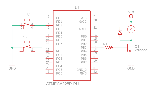
In order to control the motor's speed we will be using the Arduino UNO's Timer2 Pulse Width Modulation (PWM) module and setting the duty cycle to; 35% for SPEED1, 70% for SPEED2 and 100% for SPEED3.
When creating a project there is a flow that helps in the design process and now that we've decided on the hardware that is being used we need to create a State Transition table. We know that the actions will be based on input from the 2 switches so the table will define the States and transitions needed. The table below is the State Transition Table created for this project. There are 4 states and 6 transditions, but the Transitions from the Speed States back to Idle are similar and will not take any extra code.
| Present State | Next State (Switch #1) | Next State (Switch #2) |
|---|---|---|
| Idle | Speed1 | - |
| Speed1 | Speed2 | Idle |
| Speed2 | Speed3 | Idle |
| Speed2 | - | Idle |
While researching for this article I ran across Fizzim, The FSM Design Tool. I downloaded it and kicked the tires and wasn't real impressed but as the documentation states it's not really much of a GUI design tool it focuses more on the backend code generation portion, which I did not try as I don't do any PERL development.
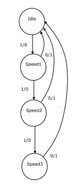
Sometimes it helps to draw a State Diagram to see a visual representation of the system that is being designed, Figure 2 is a State Diagram for the example application it shows the States, Transitions and Actions used in the project.
The traditional way to handle the transition from state to state, in a system with few states and transitions is to use a series of if/then statements or a switch statement. This works fine for a small number of states but as the logic gets more complex the code gets harder to maintain, think spaghetti code! The pseudo code that follows demonstrates one way in which the example application could have been written using a switch statement. While this solution would have been a simpler approach then the one provided it doesn't allow for much expansion.
    do forever
    {
        if(switch #1 pressed)
        {
            switch(state)
            {
                case IDLE:
                    SetSpeed(35);
                    state = SPEED1;
                    break;
                case SPEED1:
                    SetSpeed(70);
                    state = SPEED2;
                    break;
                case SPEED2:
                    SetSpeed(100);
                    state = SPEED3;
                    break;
                case SPEED3:
                    break;
            }
        }
        else if (switch #2 pressed)
        {
            SetSpeed(0);
            state = IDLE;
        }
    }
The above code would definitely do the job, with less effort but it's not very extensible and it wouldn't take much to make it unmanageable.
CFiniteStateMachine example application
Finite State Machines can be implemented in several ways, two of the more prominent ways I found during the research phase was they either use callbacks for the Entry, Post and Exit methods or they use inheritance. The CFiniteStateMachine uses inheritance, in my mind this seemed the more object oriented way to implement.
The classes in Listing 2 are the custom derived classes needed for the example application. The code is well commented so it shouldn't be to hard to follow but I will give an overview of each section to hopefully clear up any confusion should there be any.
//*
// Base state class for custom states.
// Implements the Start and Stop method that are common
//	to all derived classes.
//*
class CStateBase : public CState
{
    public:
        CStateBase() {}

    protected:
        // NOTE Initialize all states, as needed
        virtual void Initialize(uint16_t p1 = 0) override {}
        // NOTE Action to be invoked after transitioning.
        virtual void EnterAction(uint16_t p1 = 0) override {}
        // NOTE Give the Exitaction a peek at param and the value returned
        //		determines if the transition should be cancelled or not.
        //			true - Cancel operation
        //			false - continue with transition
        virtual bool ExitAction(uint16_t p1 = 0) override { return false; }

        static void Start();
        static void Stop();
};

//*
//	Derived State classes that do the work
//*
class CIdleState : public CStateBase
{
    public:
        CIdleState() {}

        void Initialize(uint16_t p1 = 0) override;
        bool ExitAction(uint16_t p1 = 0) override;
};

class CSpeed1State : public CStateBase
{
    public:
        CSpeed1State() {}

        void EnterAction(uint16_t p1 = 0) override;
        bool ExitAction(uint16_t p1 = 0) override;
};

class CSpeed2State : public CStateBase
{
    public:
        CSpeed2State() {}

        void EnterAction(uint16_t p1 = 0) override;
        bool ExitAction(uint16_t p1 = 0) override;
};

class CSpeed3State : public CStateBase
{
    public:
        CSpeed3State() {}

        void EnterAction(uint16_t p1 = 0) override;
        bool ExitAction(uint16_t p1 = 0) override;
};
The CStateBase class implements the static Start and Stop methods that all derived classes use, but since we only need a single copy the methdos are marked as static.
Listing 3 contains the code for the derived classes and shows how trivial this application is and how easy it would be to extend.
// ===============> StateBase overrides <=============
void CStateBase::Start()
{
    // Timer2 - Fast PWM, Clear OC2A on compare match
    TCCR2A |= (1 << COM2A1) | (1 << WGM20) | (1 << WGM21);

    // Prescale = 64
    TCCR2B |= (1 << CS22);
}

void CStateBase::Stop()
{
    TCCR2A = 0;
    TCCR2B = 0;

    PORTB &= ~(1 << PB3);
}

// ===============> State overrides <=================
void CIdleState::Initialize(uint16_t p1 /* = 0 */)
{
    // OC2A as output
    DDRB |= (1 << PB3);

    Stop();
}

bool CIdleState::ExitAction(uint16_t p1 /* = 0 */)
{
    Start();

    OCR2A = 0;		// 5% duty cycle

    return false;
}

void CSpeed1State::EnterAction(uint16_t p1)
{
    OCR2A = 90;		// 35% duty cycle
}

void CSpeed2State::EnterAction(uint16_t p1)
{
    OCR2A = 180;	// 70.3% duty cycle
}

void CSpeed3State::EnterAction(uint16_t p1)
{
    OCR2A = 255;	// 100% duty cycle
}

    bool CSpeed1State::ExitAction(uint16_t p1 /* = 0 */)
{
    Stop();

    return false;
}

bool CSpeed2State::ExitAction(uint16_t p1 /* = 0 */)
{
    Stop();

    return false;
}

bool CSpeed3State::ExitAction(uint16_t p1 /* = 0 */)
{
    Stop();

    return false;
}
While the classes themselves don't do a lot they demonstrate how this problem was broken down into manageable chunks, where each State has a unique role in the overall scheme.
When instantiating the classes the States don't need anything extra, we just need to declare them. The Transitions are a different story we need to tell them what State they will be tranisitioning to and the Action that will take them there.
// Finite State machine
CFiniteStateMachine fsm;

// The states
CIdleState sIdle;
CSpeed1State sSpeed1;
CSpeed2State sSpeed2;
CSpeed3State sSpeed3;

// Transitions for speed UP
CTransition ts1(&sSpeed1, SPEED_MASK);
CTransition ts2(&sSpeed2, SPEED_MASK);
CTransition ts3(&sSpeed3, SPEED_MASK);

// Transition for stopping motor, one common
//	transition for all.
CTransition ts4(&sIdle, STOP_MASK);
In the main function we add the various States to the FIniteStateMachine, add Transitions to the States that they are associated with then Set the active state to Idle and invoke CFiniteStateMachine's Initialize method that intreates through the array of states and invokes the overriden methods. In this case the CIdle's Initialize method to set the OC2A port (PB3) as output and Stop the Timer which effectively puts it in a known state.
int main(void)
{
    // Add states to FiniteStateMachine
    fsm.AddState(&sIdle);
    fsm.AddState(&sSpeed1);
    fsm.AddState(&sSpeed2);
    fsm.AddState(&sSpeed3);

    // Switch press #1 transitions, adjust duty cycle
    //	i.e. increase speed
    sIdle.AddTransition(&ts1);		// Idle -> Speed1
    sSpeed1.AddTransition(&ts2);	// Speed1 => Speed2
    sSpeed2.AddTransition(&ts3);	// Speed2 -> Speed3

    // Switch press #2 transitions, stop motor
    sSpeed3.AddTransition(&ts4);	// Speed3 => Idle
    sSpeed2.AddTransition(&ts4);	// Speed2 => Idle
    sSpeed1.AddTransition(&ts4);	// Speed1 => Idle

    // Set the active state to Idle
    fsm.SetActiveState(&sIdle);

    // Go through classes and Initialize those that need it, in this example
    //  the Idle class is the only one that needs initialization.
    fsm.Initialize();

    ...
The code in listing 5 are the interrupt handlers for Timer1 which serves as a software debouce for the 2 switches. INT0 and INT1 interrupts handle the switch inputs on the rising edge. The g_postEvent property is set to defer the posting of the event until the interrupt handler has exited.
// =================> Globals <==================
volatile uint16_t g_millis = 0;
volatile uint16_t g_ticks = 0;
volatile bool g_flg = false;
volatile uint16_t g_postEvent = 0;

// =============> Interrupt handlers <===========
ISR(TIMER1_COMPA_vect)
{
	g_millis = g_millis + 1;

	if (g_millis >= DEBOUNCE_DELAY_MS)
		g_flg = true;
}

// Motor Speed switch
ISR(INT0_vect)
{
    if (g_flg)
    {
        g_postEvent = SPEED_MASK;
        g_millis = 0;
        g_flg = false;
    }
}

// Motor stop switch
ISR(INT1_vect)
{
    if (g_flg)
    {
        g_postEvent = STOP_MASK;
        g_millis = 0;
        g_flg = false;
    }
}
The main loop checks up the g_postEvent property for a value other than 0 and if it has a valid value then that value is posted to the FiniteStateMachine's PostEvent method to handle the transition to the next state if the transition is valid. It then sets the g_postEvent value to 0 and waits for the next switch press event.
// Nothing to do here
while (1)
{
    if (g_postEvent)
    {
        fsm.PostEvent(g_postEvent);
        g_postEvent = 0;
    }

    _delay_ms(100);
}
The FSM's PostEvent method is the heart of the State Machine, it iterates through the list of transitions checking the input param against the transitions action value and if a match is found; the current states ExitAction method is called, if there is oen then the transition is madfe and the new states EntryAction method is invoked. The FiniteSstateMachine is pretty simple and leaves the heavy lifting to the derived classes.
void CFiniteStateMachine::PostEvent(uint16_t param)
{
    if (mp_currentState == nullptr)
        return;

    CTransition* ptrans = nullptr;

    volatile uint8_t len = mp_currentState->GetTransitionCount();

    for (uint8_t i = 0; i < len; i++)
    {
        ptrans = mp_currentState->mpa_transitions[i];
        // The default si to compare param to the m_value action and
        //	return true is they match, butthis behavior may be
        //	overriden if custom behavior is required.
        if (ptrans->HandleTransionEvent(param))
        {
            // Invoke the transitiong states ExitAction virtual method
            //	to provide functionality needed before transitioning to
            //	the new state and give user a chance to peek at the data
            //	and cancel the transition if return is true.
            if (!mp_currentState->ExitAction(param))
            {
                mp_currentState = ptrans->mp_target;
                // Invoke the new states virtual EnterAction method to
                //	provide initialization, as needed by new state.
                mp_currentState->EnterAction(param);
            }
            break;
        }
    }
}
I chose a uint16_t value for the TransitionAction property because most of the sensor inputs I deal with can be accessed by the 16 bit field and if not a pointer on AVR MCUs are 16 bits so they can be coerced into a uint16_t.
Summary
The CFiniteStateMachine came about as a result of a project I was working on where I used a switch statement to handle state transitions and as the scope continued to grow things got out of hand very quickly. I had a FiniteStateMachine that I had used on another project but it wasn't very generic and didn't have the functioinality I required so I did more research to learn more about State Machines and as a result of that research I developed this set of classes. The project that this will be implemented in has been an interesting one in that I've rewrote it twice, this will make three and 2 articles have spun off it, the 433MHz RF Scanner article and this one.
References
Download Here